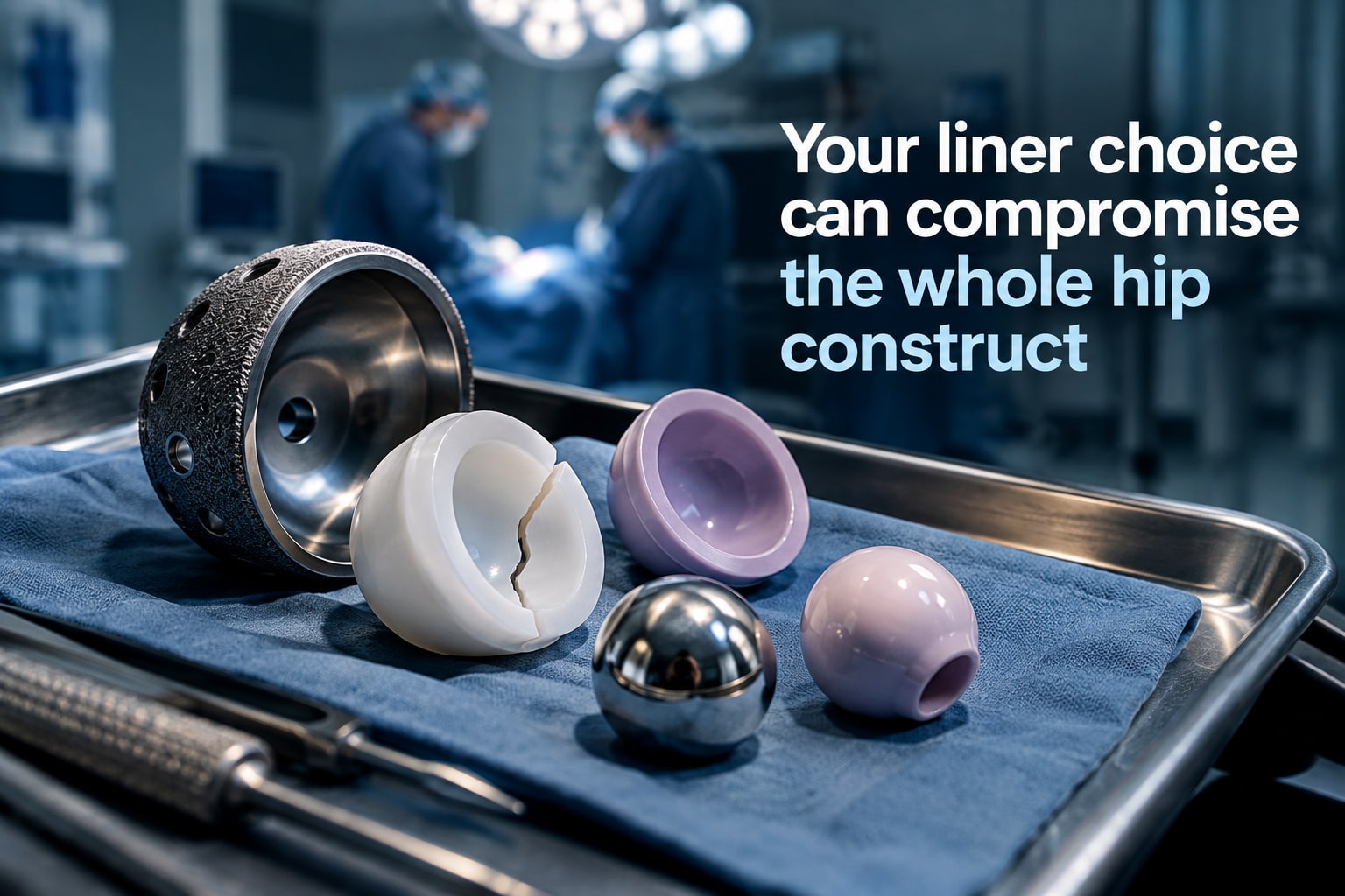
A liner can fail even when the acetabular cup looks well seated: it may dissociate, crack, wear from the backside, load at its rim, or prove incompatible with the femoral head and shell. By the end, you will know how to identify these risks, compare liner options, verify compatibility, and build practical checks into total hip replacement planning.
Key takeaways
- Match the liner to the shell manufacturer, system family, size, and locking geometry.
- Confirm the liner’s approved head size and internal diameter before surgery.
- Inspect cup position, impingement risk, liner thickness, and full construct alignment.
- Document compatibility checks before choosing a liner during primary or revision surgery.
Which liner problems can compromise a hip replacement?
An acetabular cup liner problem is any defect, mismatch, or force pattern that stops the liner locking securely, bearing smoothly, or staying aligned in a total hip replacement. Before surgery, verify the liner against the acetabular cup manufacturer, system family, shell size, locking geometry, internal diameter, approved head size, and femoral head.
A liner that appears insertable can still lack a validated load path.
Recognise these failure patterns:
- Liner dissociation, incomplete seating, or locking-mechanism failure: look for a visible gap, abnormal liner position, or sudden postoperative change on anteroposterior and cross-table lateral radiographs.
- Backside wear and micromotion: eccentric liner movement, radiolucent lines, metal-shell debris, or progressive osteolysis can reveal motion between the liner and shell even when the bearing surface looks acceptable.
- Cracking or rim fracture: new pain, clicking, instability, or a fracture line on radiographs or CT warrants urgent assessment.
- Edge loading, incorrect orientation, or incompatibility with the femoral head: excessive inclination or anteversion, contact marks, wear, impingement, and recurrent dislocation are warning signs.
| Problem | Recognition before or after surgery | Consequence |
|---|---|---|
| Loose or malpositioned shell | Migration, poor fixation, or unacceptable cup orientation on imaging | Liner exchange alone is inadequate; revise the shell |
| Femoral-side conflict | Abnormal stem version, offset, neck geometry, or head-neck impingement | Instability or liner damage despite a correctly made liner |
| Wrong liner system | Manufacturer, shell diameter, locking features, or head size do not match | Unsafe engagement or early dissociation |
| Large head in thin liner | Insufficient polyethylene around the planned head | Increased wear, impingement, or fracture risk |
How do material, thickness and head size change the plan?
Choose the liner from the stability and motion problem, not from head diameter alone. A larger head increases jump distance, but it consumes polyethylene thickness inside a given acetabular cup and can raise impingement or wear if neck geometry is unsuitable.
| Bearing option | Planning advantage | Main trade-off |
|---|---|---|
| Conventional polyethylene | Familiar, forgiving bearing | More wear over long service |
| Highly cross-linked polyethylene | Lower wear in many hip implants | Reduced thickness leaves less fatigue margin |
| Ceramic liner | Low wear and no metal-on-metal bearing | Fracture, squeaking and ceramic-head compatibility require attention |
| Metal-on-metal | Large bearing options | Metal debris, corrosion and adverse tissue reactions |
| Dual-mobility polyethylene | Large effective head and jump distance | Intraprosthetic dislocation and strict capture compatibility |
Record the liner’s actual minimum thickness, not just shell outer diameter and femoral head size. Increasing shell size can make the polyethylene thinner even when the head diameter stays unchanged; a thin liner can crack, deform or wear through under edge loading.
- Set offset with the femoral stem, neck geometry and head-neck junction; excessive or inadequate offset changes tension, impingement and stability.
- Check the planned range of motion in flexion, extension, rotation and combined positions, then test for neck-to-liner and femoral-to-cup impingement.
- Select the largest head that preserves the manufacturer’s minimum liner thickness and approved geometry, rather than choosing the largest possible head.
- Use only a liner approved for that cup shell, bearing material and head size; a joint replacement prosthesis that assembles physically can still have an unvalidated locking load path.
How do you prove that a liner fits the shell and femoral head?
A liner that drops into the shell has passed only a geometry test; it has not proved compatibility. An approved joint replacement prosthesis needs a documented match between the shell, liner and femoral head.
Record these measurements and identifiers:
- Acetabular shell manufacturer, system family, model and shell size
- Shell internal diameter and liner outer diameter, measured against the manufacturer’s size chart
- Liner locking geometry, including tabs, grooves, dovetails, taper, indexing features and capture mechanism
- Liner material, orientation option, minimum polyethylene thickness and permitted femoral head diameter
- Femoral head diameter, taper, head-neck junction size, stem model, offset and neck geometry
- For dual-mobility hip implants, the mobile-liner dimensions, capture mechanism and exact small-head compatibility
Then obtain the manufacturer’s current catalogue or instructions for use, compatibility matrix and component part numbers. The records must identify the approved shell-liner combination and the permitted head, not merely show similar dimensions. A liner from another manufacturer can be physically insertable yet lack validated locking engagement, load transfer or backside stability.
Ask for lot or serial traceability and confirmation that the selected parts belong to the same approved system family. Komal Health Care Pvt Ltd, like any supplier of hip implants, should be able to distinguish a catalogued combination from a visually similar substitute.
Do not accept a trial reduction as proof. Poor seating, incomplete locking or micromotion can create backside wear and debris, producing acetabular cup liner problems even when the articulating surface looks normal. Verify the femoral-side geometry too: stem version, offset and impingement can damage a correctly manufactured liner.
Related products
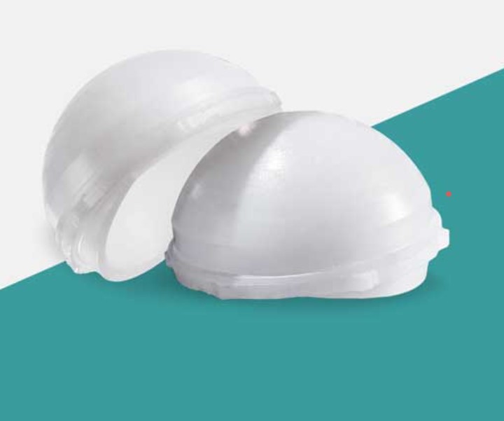 | Joint Replacement Acetabular Cup Liner Manufacturer An Acetabular Cup Liner Manufacturer specializes in producing liners that fit inside the acetabular cup during total hip replacement surgeries. View product → |
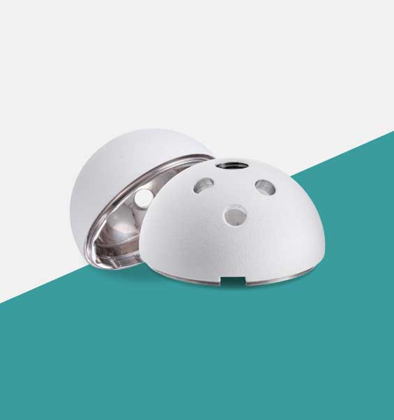 | Joint Replacement The Acetabular Cup is a key component in total hip replacement surgery, designed to fit into the hip socket (acetabulum). View product → |
How can cup position and the full hip construct damage a liner?
An acetabular cup positioned too steeply or too far anteverted exposes the liner rim, concentrating force at the edge instead of distributing it across the bearing. That edge loading accelerates polyethylene wear, can fracture ceramic, and reduces femoral-head containment, increasing instability.
The traditional Lewinnek target—40° ± 10° inclination and 15° ± 10° anteversion—does not prevent dislocation for every patient. During total hip replacement planning, account for spinopelvic motion: a stiff spine, spinal fusion, or sagittal imbalance can make a cup appear acceptable on a supine radiograph yet functionally malpositioned while sitting or standing.
Bone coverage also changes the load path. A shallow or uncovered shell transfers force to a smaller supported rim, increasing micromotion, loosening forces, and liner edge stress. Repositioning the cup to gain coverage can then create impingement or reduce stability.
Assess the femoral geometry that interacts with the cup:
- Stem version can reduce containment or bring the neck into the liner.
- Offset and neck geometry determine the available impingement-free range.
- The head-neck junction and head diameter affect impingement, jump distance, and liner thickness.
A larger head can improve stability, but it consumes more polyethylene inside the acetabular cup and may worsen contact when components conflict. Femoral or acetabular impingement can lever the liner out, deform its locking mechanism, cause acetabular cup liner problems, and produce dislocation even when the liner itself is correctly manufactured.
What checks belong in planning, revision and intraoperative decision-making?
Before surgery, obtain standing anteroposterior pelvis and cross-table lateral radiographs, then compare them with earlier films for cup migration, radiolucent lines, osteolysis, fracture, and altered inclination.
Use CT with metal-artifact reduction to define version, bone loss, shell deformation, and retained ceramic debris; investigate infection with ESR, CRP, and aspiration when loosening or unexplained pain is present.
Complete this planning checklist:
- Confirm the cup manufacturer, system family, shell diameter, locking geometry, approved liner, bearing material, head diameter, and femoral head-neck junction.
- Record the liner’s actual minimum thickness, planned offset, neck geometry, stem version, and combined anteversion.
- Assess spinopelvic motion, abductor function, leg length, impingement, and instability through the intended range of motion.
- Plan extraction tools, backup liners, shell revision components, and treatment for osteolysis or ceramic third-body particles.
During revision, inspect the shell’s fixation, orientation, taper, locking ring, and contact surfaces directly. A liner that appears insertable is unsafe without documented manufacturer compatibility and a complete locking engagement.
| Decision | Liner exchange may suffice | Shell revision is indicated |
|---|---|---|
| Stable, correctly positioned shell | Yes, with intact lock | No |
| Loose or malpositioned shell | No | Yes |
| Undamaged locking mechanism | Required | Not applicable |
| Damaged taper, deformed ring, or shell | No | Yes |
| Fractured ceramic liner | Only after debris removal and construct review | If shell or lock is damaged |
Intraoperatively, trial reduction must confirm stability without edge loading or femoral-neck impingement. A larger head is not automatically safer: it can reduce jump distance while consuming polyethylene thickness and increasing impingement. These checks protect the joint replacement prosthesis and the wider total hip replacement construct, not just one liner among the hip implants.
Frequently asked questions
Which liner problems can compromise a total hip replacement?
Defects, locking failures, shell-liner mismatches, incorrect dimensions, excessive wear, and damage can compromise fixation, bearing motion, or alignment.
How do material, thickness, and head size change the plan?
Compare the liner material, available thickness, internal diameter, and approved femoral head size with the cup system and required hip stability.
How do you prove that a liner fits the shell and femoral head?
Verify the manufacturer, system family, shell size, locking geometry, internal diameter, approved head size, and femoral head against product documentation.
How can cup position and the full hip construct damage a liner?
Cup orientation, component alignment, impingement, instability, and interactions between the liner, femoral head, neck, and shell can create damaging forces.
What checks belong in planning, revision, and intraoperative decision-making?
Use documented compatibility checks before surgery, inspect retained components during revision, and confirm seating, locking, alignment, and component condition intraoperatively.